


Page 48 - HUB-4 Magazine Issue 99
P. 48
Quarrying News
Figure 2 –
CEMA 100% Full
Design Loading
Mistracking can happen quickly and
lead to excessive downtime.
Conveyor Belt Mistracking Prevention Guidelines & Methods
R. Todd Swinderman, Former CEMA President & President Emeritus at Martin Engineering
Belt mistracking is as much a
safety issue as it is an efficiency
and spillage issue, so monitoring
belt drift to avoid contact with the
structure is critical. Operators
need to know when misalignment
becomes actionable and what to
do about it. The Conveyor
Equipment Manufacturers
Association (CEMA) updated its
System Mistracking Allowance
Guide, identifying when the belt
has drifted outside normal
operating tolerances and poses a
serious workplace hazard.[1]
Current CEMA/ISO Standards
CEMA's Guide and the International Organization for
Standardization (ISO) Standards 14890 and 15236-1 are very
similar in their recommendations for normal belt deviation
from the central path. The CEMA Guide is based on standard
CEMA components and the ISO standards on the conveyor
belt construction tolerances such as camber and troughability.
According to the ISO allowance, the conveyor belting, when
running on a correctly aligned conveyor with centered loading,
should not deviate from the central track by more than ±40
mm (±1.5 in.) for a belt width up ≤800 mm (≤31.5 in.), or by
more than ±5 percent of the belt width for widths over >800
mm with a maximum of ±75 mm (±3 in.).
CEMA Misalignment Guidelines
ISO provides an overall allowance independent of the
conveyor section or components. CEMA members realized
that there was more to the question of misalignment than the
free belt edge in the load zone and developed mistracking
guidelines based on CEMA standard components. CEMA
establishes mistracking allowances at three critical locations
of the conveyors: main pulleys, the carrying side and return
runs.
The CEMA guidelines vary from the ISO standards for 36”,
42”, 48”, 54” and 60” belt widths because the ISO
allowances exceed the CEMA standard pulley face widths and
for 54”, 60”, and 72” belt widths because the ISO Standards
exceed CEMA manufacturers’ standard return idler brackets
widths. These variances are easily overcome at the design
stage by specifying wider pulley faces, offset return drop
brackets and providing the required structural clearances.
Carrying Side Mistracking Allowance
Carry side mistracking is usually not constrained by the idler
roll length or load zone structural supports but rather by the
possibility of spillage. [Fig. 1]
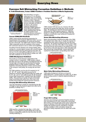
CEMA standard 100% full area, As, is based on the idler
geometry, the standard belt edge, Bwe, and the surcharge
angle. The standard area times the belt speed and bulk
density give the CEMA standard capacity, Q. CEMA best
practice is to design for 85% of the theoretical 100% full
loading to accommodate surge loading and changing bulk
material properties.
Return Side Mistracking Allowance
Return side mistracking is limited by the width of the CEMA
502 standard return rollers. [Fig. 3] Usually, the structure for
mounting the return rollers is based on the carry idler base
dimensions. The standard mounting brackets for return rollers
are very close to the ends of the rollers in most designs. If the
belt travels into the return bracket it can quickly be cut in two
by the friction of the belt edge which is often embedded with
fines and acts like a hacksaw blade. Serious injuries have
resulted from failed brackets causing falling return idlers.
Figure 1 –
CEMA Carry Side
Mistracking
Allowances
Main Pulley Mistracking Allowances
CEMA pulley misalignment tolerances are based on
ANSI/CEMA B105.1 standard pulley face widths. [Fig. 4] When
greater tracking variance is required, engineered pulleys are
an option.
Figure 4 –
CEMA Pulley
Mistracking
Allowances
Figure 1 –
CEMA Carry Side
Mistracking
Allowances
Proper Belt Loading
Operators and maintenance personnel should be trained on
how overloading and off-center loading affect mistracking.
Belt tracking is primarily through gravity (center loading) and
friction (a minimum of 50% belt contact with the idlers).
Spillage and carryback must be controlled for consistent
tracking as buildup on idlers and pulleys changes the
geometry of rolling components and can reduce belt-to-idler
friction.
CEMA specifies a standard belt edge (Bwe = 0.055 x Belt
Width + 0.9 in) designed to prevent spillage due to belt sag
between carrying idlers outside the load zone when the belt is
centrally loaded.[Fig. 2]
| p48 |
www.hub-4.com July/August - Issue 99

