Storage Sorrow: Loosening Silo & Hopper Clogs in Cement Plants


Brad Pronschinske, Global Air Cannon Product Manager / Martin Engineering
The drumming sound of bulk material hitting the metal sides of a hopper, bin or silo during loading is the sweet sound of production. If the noise becomes muffled, it likely indicates that the vessel is filling up, or it could signal the presence of buildup on the inside walls or discharge gate.
Once coarse material adheres, the buildup is generally fast and dense, eventually resulting in downtime to remove. When operators notice material is no longer flowing, spilling over the edge or backing up on conveyors, they know a clog has formed. Seeking ways to address it quickly without the proper tools or training can also be the moment when workplace safety degrades.
Flow aids are engineered to safely clear and prevent clogging, promote material flow and avoid costly downtime. To know what technology will work best for a specific application, the first step is understanding how, where, when and why clogs happen in any given vessel or transfer point. The second step is removing any worker involvement in clearing the clog, aside from pushing a button to activate the flow aid if it isn’t automated or controlled by logistical software.
Clogging, Loads, and Carry Weight
Although silos are designed to hold a certain volume of a particular material, hoppers generally exist to consolidate and direct the material flow. In both, an awareness of the maximum load is important. Some operators match the hopper size to transport bin size (for trains, trucks, etc.), repeatedly filling and emptying them. This makes load requirements especially important in those cases, since capacity is reached dozens or hundreds of times per day under many conditions. When working with bulk solids, environments with high moisture and freezing regularly experience clogging. Wide variations in the size and shape of material can also affect the flow characteristics, leading to buildup and clogs.[1]
Hopper configurations vary greatly, so appropriate flow aid selection depends on the application.
If a hopper is not designed to carry the material load at full capacity, then a sudden surge of material or a clog can lead to danger. Even if a vessel is engineered properly, abrasion from loading can cause the walls of the hopper or silo to wear thin over time, decreasing their ability to carry the weight, potentially causing them to buckle and possibly injure anyone working near the structure.
Operators are recommended to reference section 313-97 of the American Concrete Institute (ACI) structural standards to determine the proper design of the equipment. [2] The authors define “loads” as follows:
Dead load – The total weight of the structure, including attached items and equipment supported by the structure.
Live load – Forces exerted from stored material, including high and low pressures caused by flow. Essentially, that includes anything independent of the structure, including snow, positive and negative air pressure, wind or seismic load and forces from materials stored against the outside.
Thermal Load - Caused by temperature differences between the inside and outside faces of the wall.
Settling Load – Force from uneven settling of the structure.
Weather, weight/size of the material, structural design and load distribution are all factors that can lead to clogging and/or an overcapacity situation. The weight of the material can contribute significantly to structural integrity and load distribution, as well as the force of the material once it is discharged. The discharge surge can overwhelm the bin or conveyor onto which the material is flowing, so understanding the weight of the material in the clog is important. Once the clog has been detected, the weight of the clogging can be calculated using a load that is equivalent to the capacity of the chute or vessel in question, with due reference to the slope angle. The material normally within the chute or vessel may be deducted. The actual bulk weight must be taken for the calculation.[3]
Discharge Point Geometries
Discharge channels come in varying shapes, depending on the vessel and the material flow characteristics. [Fig1] Spouts that are narrow, such as those found on conical or pyramidal shapes, direct flow in a vertical column either into a chute or specific loading area. Slotted spouts, like those found on the wedge or transition shapes, distribute material in a narrowly defined line for loading onto conveyors or into containers (trains, trucks, etc.)
The geometry of a vessel must match that of the discharge point or it will be prone to clogging. Cement producers carefully choose discharge point shapes based on a series of load and flow factors. The slope angles in discharge point geometries can contribute to clogging based on material characteristics, the specifications of the application or the placement of the vessel.
These discharge points can feature gates or grates that stop or separate the material. Gates halt material flow for incremental filling of transport bins on a train or truck. Grates can be used to slow or direct the flow of material when loading onto a conveyor. Either way, operators find that they can exacerbate clogging by stopping or slowing material at a structural choke point of the vessel.
Unsafe Practices
Once a clog has been detected, there are several unsafe practices that at the time may seem harmless, but frequently cause serious worker injuries or fatalities year after year. The two main causes of injury are sudden discharge of adhered material and entrapment.
One unsafe method is beating the vessel walls with mallets or other objects to loosen adhered material. Over time, the more the walls are pounded, the worse the situation becomes, as the bumps and ridges left in the wall from the hammer strikes will form ledges that provide a place for additional material accumulations to start.
Another hazardous practice is poking or lancing underneath the clog at the discharge point. This can result in a sudden surge of falling material, burying or crushing the worker(s) below.
Perhaps the most prevalent cause of worker injuries and fatalities is confined space entry of the vessel. Along with potentially sinking into the material in the center, the material could be bridging and suddenly release. If a worker enters the vessel and stands on the volatile bridge, a sudden discharge could pull the worker into the cavity. Another serious hazard of confined space entry is material buildup on the sides of the vessel, reaching higher than the worker. This buildup could fall from above, causing serious injury or burial.
Air lancing the clog from the mouth of the vessel at the top is an option many operations have chosen, but guardrails are highly recommended. The reach of the lance and the pressurized air stream must match the size of the vessel. Workers can fall in trying to reach the lance down to the clog, even if guardrails are present.
All these hazards can be avoided by introducing flow aids to the vessel to mitigate clogs, promote material flow and reduce downtime.
Flow Aids = Greater Safety with Less Downtime
As the term implies, flow aids are components or systems installed to promote the transport of materials through a chute or vessel, controlling dust and spillage. Flow aids come in a variety of forms, including rotary and linear vibrators, high- and low-pressure air cannons and aeration devices, as well as low-friction linings and special chute designs, to promote the efficient flow of bulk materials.
These modular systems can be combined in any number of ways to complement one another and improve performance. The components can be used for virtually any bulk material or environment, including hazardous duty and extreme temperatures. One of their primary advantages is that an operation can obtain a level of control over the material flow that is not possible any other way.
When employing flow aids, it’s critical that the chute and support components are sound and the flow aid be properly sized and mounted, because the operation of these devices can create potentially damaging stress on the structure. A properly designed and maintained vessel will not be damaged by the addition of correctly sized and mounted flow aids.
It’s also important that any flow aid device be used only when discharges are open and material can flow as intended. The best practice is to use flow aids as a preventive solution to be controlled by timers or sensors to avoid material buildup, rather than waiting until material accumulates and restricts the flow. Using flow aid devices in a preventive mode improves safety and saves energy, since flow aids can be programmed to run only as needed to control buildup and clogging.
Engineered Vibration
The age-old solution for breaking loose blockages and removing accumulations from chutes and storage vessels was to pound the outside of the walls with a hammer or other heavy object. A better solution is the use of engineered vibration, which supplies energy precisely where needed to reduce friction and break up a bulk material to keep it moving to the discharge opening, without damaging the chute or vessel. The technology is often found on conveyor loading and discharge chutes, but can also be applied to other process and storage vessels, including silos, bins, hoppers, railroad cars, screens, feeders, cyclones and heat exchangers.
There is another innovative solution that prevents carryback from sticking to the rear slope of a discharge chute. The dribble chute uses material disruption to reduce friction and cause tacky sludge and fines to slide down the chute wall and back into the main discharge flow. By addressing these issues, operators can experience a reduction in maintenance hours, equipment replacement and downtime, lowering the overall cost of operation.
Air Cannons
One solution for managing material accumulation in chutes and vessels is the low-pressure air cannon, pioneered and patented by Martin Engineering in the 1970s. It uses a plant’s compressed air to deliver a powerful discharge to dislodge the buildup. Cannons can be mounted on metallic, concrete or wood surfaces. The basic components include an air reservoir, fast-acting valve with a trigger mechanism and a nozzle to distribute the air in the desired pattern to clear the accumulation most effectively.
The device performs work when compressed air (or some other inert gas) in the tank is suddenly released by the valve and directed through an engineered nozzle, which is strategically positioned in the chute, tower, duct, cyclone or other location. Often installed in a series and precisely sequenced for maximum effect, the network can be timed to best suit individual process conditions or material characteristics. The air blasts help break down material accumulations and clear blocked pathways, allowing solids and/or gases to resume normal flow. In order to customize the air cannon installation to the service environment, specific air blast characteristics can be achieved by manipulating the operating pressure, tank volume, valve design and nozzle shape.
In the past, when material accumulation problems became a recurring issue, processors would have to either limp along until the next scheduled shutdown or endure expensive downtime to install an air cannon network. That could cost a business hundreds of thousands of dollars per day in lost production. Many designers now proactively include the mountings in new designs so that a future retrofit can be done without hot work permits or extended downtime.
New technology has even been developed for installing air cannons in high-temperature applications without a processing shutdown. This allows specially-trained technicians to mount the units on furnaces, preheaters, clinker coolers and in other high-temperature locations while production continues uninterrupted.
Valve Replacement
Over time, the valve in an air cannon will wear, even under normal conditions, and it’s common practice to refurbish them rather than replace with new ones. Because clearances and fits are critical to proper operation, it’s recommended that flow aid devices be rebuilt and repaired by the manufacturer, or that the manufacturer specifically train plant maintenance personnel to properly refurbish the equipment.
To simplify the process and avoid system downtime, one manufacturer has created a program to supply factory-rebuilt air cannon valves that carry the same warranty as new valves. Customers can receive a standard pallet-sized container with six refurbished valves, so there’s no need for users to rebuild worn-out components. The changeout can be accomplished in just ten minutes, at less than half the cost of new valves. The used valves are shipped back to the company, where the units are rebuilt to as-new condition by factory-trained technicians. Customers save time and money, with no need to stock repair parts or provide the training / labor to rebuild.
Case Study
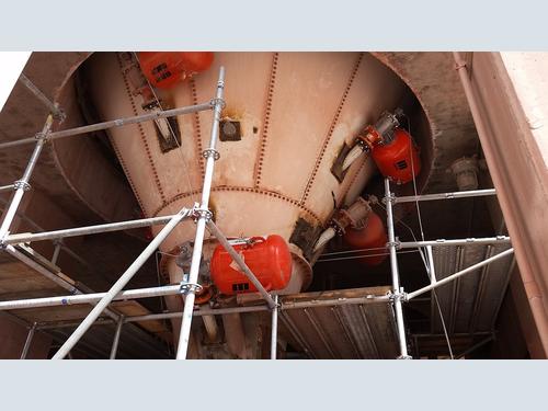
A cement plant in Arizona was experiencing clogging in its limestone silo. With a capacity of 660,000 tons (598,741 metric tons) of high-quality Portland cement per year, weekly downtime due to clogging became an issue. Excessive rain January through March caused the limestone being extracted from the nearby quarry to have elevated moisture levels, exacerbating the situation.
Air cannons were already used successfully elsewhere in the plant, so operators had developed confidence in their performance as a solution. Five 70-liter (88 lb/40kg) air cannons were strategically placed around the vessel. Installed with a 4-inch (101 mm) valve, three were placed on the lower incline of the cone at a 30º downward angle against the 60º slope in the 6 and 12 o’clock positions. In the 3 o’clock position, one air cannon was situated at the 2-foot-wide shaft, and another was added to the upper silo to aid in loosening material. The cannons use a positive-acting valve that is triggered by a solenoid located a safe and convenient distance -- up to 200 feet (61 meters) -- from the vessel.
The new valve design produces about twice the blast force output of the previous valve generation, while using about half the compressed air volume. It also fires only in response to a positive surge of air sent by the solenoid, eliminating the risk of an accidental discharge.
Since the installation, there has been no unscheduled downtime due to clogging, which has greatly increased production, especially through heavy weather periods. When buildup is detected, workers no longer are required to get close to the area to resolve it, increasing plant safety and reducing the number of man-hours required to maintain the silo.
“This equipment upgrade has paid for itself many times over,” said a manager close to the project. “We are extremely happy with the results.”
Let The Silo Flow
Flow aid devices deliver force through the chute or vessel and into the bulk material. Over time, components will wear, or even break, under normal conditions. Most of these devices can be rebuilt to extend their useful life. Because clearances and fits are critical to proper operation, it’s recommended that flow aid devices be rebuilt and repaired by the manufacturer, or that the manufacturer specifically train plant maintenance personnel to properly refurbish the equipment.
References
[1] Hafez, A., Liu, Q., Finkbeiner, T. et al. “The effect of particle shape on discharge and clogging.” Sci Rep 11, 3309 (2021). https://doi.org/10.1038/s41598-021-82744-w
[2] John Carson and David Craig, “Standard Practice for Design and Construction of Concrete Silos and Stacking Tubes for Storing Granular Materials”. American Concrete Institute, ACI 313-97. Jenike & Johanson, Tyngsboro, MA. 1998 http://civilwares.free.fr/ACI/MCP04/313_97.pdf
[3] “Foundations for Conveyor Safety”. Ch.2, pg. 44. Martin Engineering. Worzalla Publishing Company, Stevens Point, Wisconsin. 2016. https://www.martin-eng.com/content/product/690/safety-book